Miller Curbers can be equipped with one of four (4) different extrusion auger diameters.
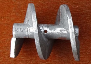
These diameters are 5″, 6″, 8″ and 10″.
Auger assemblies are interchangeable between all Miller Curber models with the exception of the 10″ diameter assembly which is only available on the higher horsepower models Mc850 and MC900.
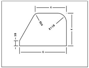
Each of these auger assemblies works best with a particular range of curb sizes, measured in cross sectional area. The relationship between the cross sectional area of the curb and auger size is critical and must be given careful consideration when matching a particular curb with the correct auger assembly.
IMPROPER SIZING CAN CAUSE EXCESSIVE COMPONENT WEAR, REDUCED LIFE, POOR PERFORMANCE OR COMPLETE FAILURE TO OPERATE.
The following table is a general guide to choose the correct auger assembly for your application. Always consult the factory for curb form and auger size recommendations. Some curb shapes may require deviation from this chart.
Because most extruded curb is between 33 and 55 square inches in cross sectional area 90% of all machines are equipped with the standard 6″ diameter auger.
Click to View below Table (Large)
| Auger Diameter |
Minimum Area |
Maximum Area |
Minimum Height |
Maximum Height |
Minimum Width |
Maximum Width |
| 5″ | 18 | 32 | 3 1/2″ | 6″ | 5″ | 9″ |
| 6″ | 33 | 55 | 4″ | 10″ | 6″ | 14″ |
| 8″ | 56 | 119 | 6″ | 18″ | 8″ | 18″ |
| 10″ | 120 | 220 | 8″ | 18″ | 10″ | 18″ |
The most common mistake when sizing forms and augers is choosing a curb form which is too small for a particular auger size.
For example, a curb shape that is a simple rectangle 6″ wide x 4″ high would have a cross sectional area of 24 square inches. This puts it clearly in the 5″ diameter auger range.
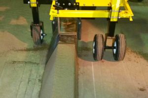
The second most common mistake when sizing forms and augers is choosing a form that is too large for a particular auger size. Under sizing the auger will not cause problems as severe as over sizing but will affect machine performance. Curb density and finish may be adversely affected and extrusion speed will be reduced. It is possible to add 5-10% to the recommended upper limit for any given auger size and still extrude satisfactorily. In the most severe case of an undersized auger the machine may discharge enough material into the form to propel itself, but inadequate density may result in a loose curb with open finish and surface voids that may not stand. Always consult the factory for recommendations on proper auger size and curb form choices.
Other Auger Considerations
The auger assembly can be placed on either the right or left side of the machine. The machine’s right and left are determined by standing at the end of the machine where the curb form is attached and looking at the open end of the form. From this perspective, if the form and auger assembly are on the left then this would be considered left hand extrusion. Unless otherwise specified at the time of ordering all machines are equipped for left hand extrusion.


